How to Design an Induction Heating Coil
- 13 Mar, 2023
- 6523 views
A typical induction heating machine consists of a Power Supply, LC (induction heating coil and capacitor) resonant section, and Load (workpiece). An Induction coil transfers oscillation current which is generated by LC resonant circuit to the workpiece.
The induction heating coil is specifically shaped with a copper tube which alternating electrical current is passed through, creating a variable magnetic field. Magnetic metal parts are placed within, through, or close to the induction heating coil, without touching the coil, and the variable magnetic field that is generated causes friction within the metal causing it to heat.
An induction coil is composed of three parts, namely the connection plate, the coil lead, and the heating coil. The connection plate is the part that connects and fixes the induction coil to the induction heater and the coil lead is the part that connects the heating coil to the connection plate. Its length is determined by the distance between the heating coil and the induction power supply. The heating coil is the part that does work. It generates an induced electromagnetic field, induces eddy currents on the workpiece, and heats the workpiece.
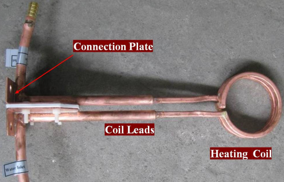
The induction coil is also an inductor, the inductance of an induction coil = inductance of coil lead × 2 + inductance of the heating coil. The power output by the induction equipment is distributed directly between the two because they are in series. Whoever has a larger inductance will be allocated more power. The inductance of the coil lead does not work but only produces reactive power. Therefore, how to reduce the inductance of the coil lead is the key to making a highly efficient induction coil
As one of the important elements of an induction heater, the design of the inductor is very critical. There are 7 Key Points for Induction Coil design:
1. Shape imitation
The shape of the induction coil should match the shape of the workpiece as much as possible
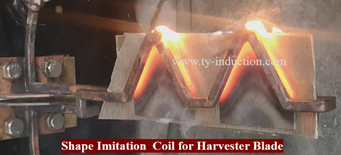
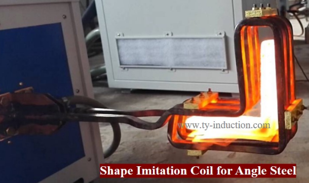
2. The current flow direction between adjacent turns should be the same
The adjacent turns of the heating coils of the induction coil that are close to each other must have the same current direction. If they are not consistent, the electromagnetic fields will cancel each other. The Cancellation effect must be avoided
3. Appropriate distance between the heating coil and the workpiece.
This point is very important. For the convenience of operation, many users always make a large gap between the heating coil and the workpiece. The gap between the induction coil and the workpiece will cause the electromagnetic field generated by the induction coil to be only partially coupled to the workpiece. The electromagnetic field that is not coupled to the workpiece passes through the gap between the induction coil and the workpiece, generating reactive power without doing work. The larger the gap, the greater the reactive power and the lower the coupling efficiency. For hardening, the gap between the induction coil and the workpiece is usually 2-4mm
4. Appropriate number of turns ensure good matching
In the case of ensuring a reasonable gap between the induction coil and the workpiece, the number of turns of the induction coil is mainly determined according to the matching status of the induction power supply. If it shows the load is heavy, reduce the number of turns of the induction coil or increase the gap between the induction coil and the workpiece; if the induction heating system shows a light load, increase the number of turns of the induction coil.
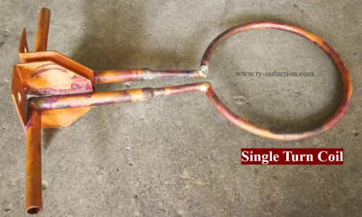
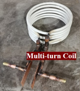
5. Try to use an internal magnetic field for heating
According to the proximity effect and ring effect of high-frequency current, the flux of the internal magnetic field is the most concentrated and the coupling efficiency is the highest, so try to use ring induction coils instead of open induction coils.

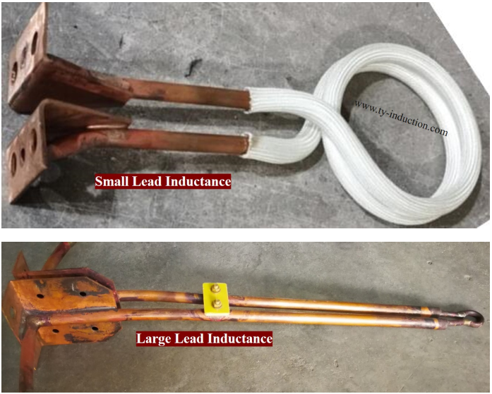
6. Minimize the length and inductance of the coil lead
This is also critical. The coil lead does not do work but produces reactive power loss and resistance loss. It is very important to reduce the reactive power loss of the coil lead. Usually, the coil lead is made of a copper plate with a width of 40-80mm and a thickness of 2-4mm, and an insulating sheet with a thickness of 0.5-1mm is used to insulate the two copper plates. Cooling copper pipes should be welded on the copper plate. This minimizes the inductance of the coil lead.
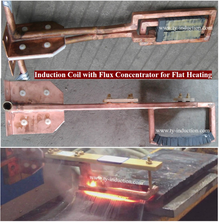
7. Inner hole and flat heating (external magnetic field heating) need to add flux concentrator in the heating coil to improve the coupling efficiency

In conclusion, the design of the induction coil can directly affect the efficiency of induction heating equipment and customer satisfaction.
- Category:
- Arts & Culture
- No comments

